What is Layer 2 Switching Loop?
A physical loop occurs when there are multiple active connections (links) between two switches in a network. This can lead to a broadcast storm, where data circulates endlessly, causing network chaos.
For example, in a network with four interconnected switches, there are two sets of connections between a computer (Workstation) and a server (Web Server):
- Main Connection : Switch-1 > Switch-2 > Switch-4
- Backup Connection : Switch-1 > Switch-3 > Switch-4
Workstation is connected with Switch-1 and Web Server is connected with Switch-4.
To ensure smooth operation, only one of these connections should be active at a time to prevent switching loops that can disrupt the network.
Think of a switch as a smart traffic manager for data. It learns and retains the MAC addresses of connected devices in a table called the CAM table.

Now, let's break down how a switching loop occurs step by step:
- The Workstation sends a broadcast frame to reach the Web Server. Since the Workstation is directly connected to Switch-1, the frame is initially forwarded to Switch-1
- Switch-1, not knowing where the Web Server is located, sends the frame out to all its connected ports except for the one where the frame originated . This means the Workstation won’t receive its own frame in this broadcast.
- Switch-2 and Switch-3, connected to Switch-1, receive copies of the frame.
- Switch-2 and Switch-3 each attempt to locate the destination of the frame and, in doing so, broadcast the frame once again. They exclude the port from which they received the frame. This means Switch-1 won’t receive the frame again from Switch-2 and Switch-3.

- Switch-2 sends the frame to PC-1 and Switch-4.
- Switch-3 sends the frame to PC-3 and Switch-4.
- Switch-4 receives two copies of the frame through different paths:
- For the first copy (Copy-1), the frame travels from Switch-1 (Port-15) to Switch-3 and then to Switch-4 (Port-22).
- For the second copy (Copy-2), the frame takes the path from Switch-1 (Port-16) to Switch-2 and then to Switch-4 (Port-23).
- Switch-4 broadcasts both copies of the frame to PC-2, the Web Server, and all connected ports except for the source port. Because of the redundant paths in the network, the broadcast frame takes two routes and eventually comes back to Switch-1.
- For the first copy of the frame (Copy-1), it travels through Switch-4 (Port-23) > Switch-2 > Switch-1 (Port-16).
- For the second copy of the frame (Copy-2), it follows the path Switch-4 (Port-22) > Switch-3 > Switch-1 (Port-15).
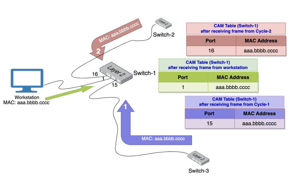
Since Switch-1 still doesn’t have the MAC address information for the Web Server, it once again broadcasts both copies of the frame. This leads to the creation of two circulating paths in the network. Unfortunately, this situation causes the Workstation to receive its own broadcast frame.
- Unaware of the loop, switches keep forwarding the frame in a loop, including the port from which they received the frame.
The looping of frames triggers a broadcast storm, where more and more frames circulate throughout the network. This excessive traffic consumes network bandwidth and resources, resulting in chaos and disruptions. To prevent such loops and ensure network stability, the Spanning Tree Protocol(STP) is deployed.