Understanding of Spanning Tree Protocol (STP)
What is Spanning Tree Protocol(STP)?
In computer networking, especially in Ethernet networks, the Spanning Tree Protocol (STP) plays a crucial role in preventing loops and ensuring the stable and efficient operation of the network. Developed by Dr. Radia Perlman in 1985, STP has become a fundamental part of the IEEE 802.1D standard.
Ethernet networks are susceptible to loops, which can lead to broadcast storms and network inefficiencies. Layer-2 Network Loops occur when there are redundant paths between switches, creating multiple routes for data to traverse. While redundancy is crucial for fault tolerance, it can lead to loops without proper management. STP addresses this issue by identifying and blocking redundant paths, thus establishing a loop-free topology.
Basic Concepts of Spanning Tree protocol (STP):
- Bridge Protocol Data Units (BPDUs): BPDUs serve as frames carrying vital information regarding the spanning tree protocol (STP). When a switch wants to share this information, it sends out BPDUs using its origin port’s MAC address. These BPDUs are directed to a multicast address with a designated destination MAC. Essentially, BPDUs play a key role in the communication process that ensures the proper functioning and stability of the spanning tree protocol within a network. Explore the role of BPDUs in conveying vital information between switches, aiding in topology determination.
- Bridge ID: The Bridge ID is an 8-byte field, comprised of both the bridge priority (2 bytes) and the Base MAC address (6 bytes) of a networking device.
- Bridge Priority: The Bridge Priority itself is a default priority assigned to each switch, typically set at 32768.
- Root Bridge: The root bridge in a network, determined by the Spanning Tree Protocol, establishes a central reference point, preventing loops and ensuring a hierarchical structure. Generally root bridge is determined by the lowest Bridge ID.
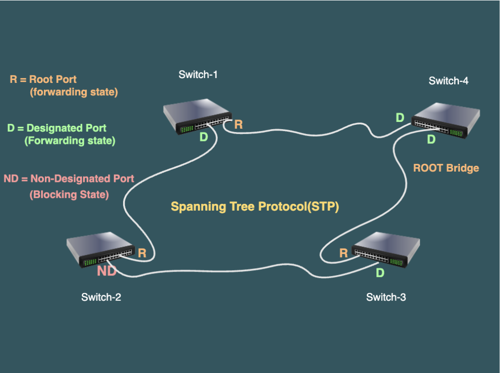
- Role of Ports: STP designates roles to ports based on their functionality within the network. Key roles include Root Port, Designated Port, and Non- Designated Port, each contributing to the establishment of a stable and efficient topology
- Designated Port: The designated port is the one that transmits the most optimal Bridge Protocol Data Unit (BPDU). In other words, ports connected to the root bridge will be in a forwarding state because they send the most favorable BPDU.
- Non-Designated Port: A non-designated port on a network switch or bridge is a port that is not selected as the designated port for a specific network segment. These ports are typically in a blocking state to prevent loops, serving as backup paths in case the designated port fails.
- Root Port: The root port on a non-root bridge is the port that gets the most favorable Bridge Protocol Data Unit (BPDU)
Following is the Criteria for selecting the root port:
- Lowest path cost to reach the root bridge.
- Lowest sender bridge ID.
- Lowest sender port ID.

Port States for Different Port Roles:
Each interface on a bridge using spanning tree exists in one of these states:
- Blocking: The interface is inactive in frame forwarding, preventing loops in the network.
- Listening: The initial transitional state after blocking, where the spanning tree allows the interface to potentially participate in frame forwarding.
- Learning: The interface readies itself to engage in frame forwarding, acquiring information about the network.
- Forwarding: The interface actively forwards frames, facilitating regular data transmission.
- Disabled: The interface is inactive in the spanning tree process due to reasons such as port shutdown, no link on the port, or the absence of a spanning-tree instance on the port.
How STP Operates in Layer-2 Network:
The Spanning Tree Protocol operates in two key steps:
- Root Bridge Election: Here switches determine the central bridge with the lowest Bridge ID.
- Root Port Election: Here each switch selects the most optimal port for forwarding traffic toward the root bridge.
1. Root Bridge Election process:
The root bridge is determined by the bridge with the lowest Bridge ID. All the switches in the network declare themselves root bridges and start exchanging their own BPDU. When switches share default priorities, a tiebreaker based on MAC address becomes necessary.
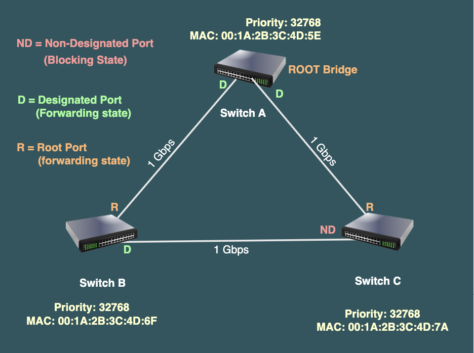
Consider a scenario where we have three switches, namely Switch A, Switch B, and Switch C, all initially set with the same default priority. In this case, the following scenario will unfold:
- Initial Setup:
- Switch A, Switch B, and Switch C start with default priorities (32768) and exchange BPDUs to determine the root bridge.
- Bridge Priority Comparison:
- If all three switches have the same default priority, a tie occurs.
- MAC Address Tiebreaker:
- Suppose Switch A has MAC address 00:1A:2B:3C:4D:5E.
- Switch B has MAC address 00:1A:2B:3C:4D:6F.
- Switch C has MAC address 00:1A:2B:3C:4D:7A.
- Result:
- Switch A, having the lowest MAC address, becomes the root bridge.
- Hierarchy Determination:
- Switch A becomes the root bridge, and the other switches adjust to this hierarchy based on their proximity and connectivity.
2. Root Port Election process:
Root port elected on non- root bridge by determining the path cost in a network. Path cost is calculated using the following formula:
Path Cost=Link Cost+Cost to Root Bridge
The link cost is a predefined value based on the speed of the link, and the cost to the root bridge is the cumulative cost from the local switch to the root bridge. The switch selects the path with the lowest path cost to reach the root bridge, ensuring optimal and efficient data transmission within the network.
Let’s consider an example where Switch A and Switch B are connected through a Gigabit Ethernet link. In the context of Spanning Tree Protocol (STP), the path cost is calculated based on the link speed.
Assuming the link speed is 1 Gbps, the link cost for Gigabit Ethernet is typically 4. According to the IEEE 802.1D standard, the path cost is calculated as follows:
Path Cost=Link Cost+Cost to Root

If Switch A is the root bridge, and Switch B wants to calculate the path cost to the root bridge (Switch A), the cost would be:
Path Cost=4+0
In this example, the cost to the root bridge (0) is considered since Switch A is the root bridge. Therefore, the path cost from Switch B to the root bridge (Switch A) is 4. This path cost is crucial in STP to determine the optimal path for forwarding traffic within the network.
Best Practices for STP Configuration:
- Bridge Priority Adjustment
- Function: Bridge Priority Adjustment is a crucial mechanism within the Spanning Tree Protocol (STP) that enables network administrators to influence the selection of the root bridge. By assigning priority values to individual bridges, administrators can control the path selection process and improve overall network efficiency.
- Purpose: The primary purpose of Bridge Priority Adjustment is to enhance the stability and performance of the network topology. By strategically assigning priorities to bridges, administrators can influence the root bridge election, ensuring that the most suitable bridge assumes the central role. This optimization minimizes convergence times and promotes a resilient network architecture.
- Guard Root Function:
- Function: Spanning Tree Guard Root is a mechanism that safeguards the network’s root bridge position. It prevents undesired designated ports from becoming root ports by immediately placing such ports into the Blocking state.
- Purpose: The Guard Root feature ensures that the root bridge remains secure and stable. By preventing undesired ports from influencing the root bridge election, network administrators can maintain control over the network’s core, optimizing its overall performance.
- BPDU Guard Function:
- Function: BPDU Guard is a security mechanism that monitors designated ports for unexpected Bridge Protocol Data Units (BPDUs). If unexpected BPDUs are detected, the port is immediately placed into the Errdisable state, preventing potential misconfigurations.
- Purpose: The primary purpose of BPDU Guard is to enhance network stability and security by identifying and isolating ports that may compromise the integrity of the spanning tree topology. It acts as a fail-safe mechanism against misconfigurations and unauthorized devices entering the network.
- PortFast Function:
- Function: PortFast is a feature designed to accelerate the transition of access ports to the Forwarding state, bypassing the traditional STP states (Blocking, Listening, and Learning). It is typically applied to ports connected to end devices, such as computers or printers.
- Purpose: PortFast aims to reduce network convergence times, particularly for access ports where loops are less likely to occur. By swiftly moving ports to the Forwarding state, PortFast enhances network responsiveness and ensures minimal downtime for end-user devices.
- Defining Point-to-Point Link Type:
- Function: The Point-to-Point link type in Spanning Tree Protocol is a configuration applied to network links where there are only two connected devices, eliminating the need for the protocol to engage in certain time-consuming negotiations that are typically required in shared or multi-access environments.
- Purpose: The primary purpose of configuring a Point-to-Point link type is to streamline the STP operation on specific links. By acknowledging that only two devices are connected, STP can optimize its convergence process, reducing the time required to transition ports between different states.
Varient of Spanning Tree:
Spanning Tree Protocol (STP) has evolved over time, and various enhancements and improvements have been made to address the limitations of the original standard. Here are some STP variants or extensions:
Classic STP(IEEE 802.1D):
- Provides loop prevention by blocking redundant links in the network.
- Slow convergence and recovery times.
Rapid Spanning Tree Protocol – RSTP(IEEE 802.1w):
- An improvement over classic STP, RSTP reduces the convergence time by actively and quickly transitioning ports to the forwarding state.
- Faster convergence is achieved through the introduction of new port roles (discarding and learning).
- Compatible with classic STP, so it can coexist with older switches in the network.
Multiple Spanning Tree Protocol – MSTP(IEEE 802.1s):
- Designed to overcome the limitations of having a separate instance of STP for each VLAN.
- Allows mapping multiple VLANs to a single spanning tree instance, reducing the complexity of managing multiple instances.
- Enhances scalability and simplifies configuration in large VLAN environments.
Per-VLAN Spanning Tree (PVST) and Rapid PVST:
- Cisco’s proprietary extensions to STP, allowing for a separate spanning tree instance for each VLAN.
- PVST+ is backward compatible with IEEE 802.1Q (VLAN trunking) and allows for faster convergence times within individual VLANs.
- Rapid PVST builds upon PVST, introducing rapid convergence features similar to RSTP.
When configuring STP on Cisco devices, it’s essential to consider the specific requirements of the network, compatibility with existing equipment, and the desired balance between protocol adherence and proprietary enhancements. RSTP and MSTP are widely adopted in modern networks due to their faster convergence times and improved scalability. However, the choice of STP variant depends on the network’s architecture, equipment, and the need for specific features.
Redundancy Management:
- EtherChannel: EtherChannel bundle multiple physical links into a single logical link, enhancing redundancy without compromising network stability.
- STP Tuning: Fine-tune STP parameters to adapt the protocol to specific network requirements, minimizing convergence time and improving overall performance.
Troubleshooting Tips: Common Network Issues and Solutions
- Topology Changes:
- Problem: If you’re experiencing frequent changes in network topology due to physical link fluctuations, it’s likely causing disruptions.
- Solution: To address this, consider physically breaking the loop by shutting down or unplugging the cable causing the instability.
- Bridge Priority Misconfiguration:
- Problem: Before deploying any switch in the network, ensure that the bridge priority is configured correctly. Failure to do so may lead to disruptions in Spanning Tree Protocol (STP) operation.
- Solution: Take the necessary steps to configure bridge priorities to maintain a stable network environment.